


 |
IEC 61347-1-2012 Figure 3 Test Circuit for Controlgear / Light Measurement Equipment
Product Details:
| Place of Origin: | China |
| Brand Name: | KingPo |
| Certification: | Calibration certificate |
Payment & Shipping Terms:
| Minimum Order Quantity: | 1 |
|---|---|
| Price: | To be quoted |
| Packaging Details: | safety carton pack or plywood box |
| Delivery Time: | 7 working days |
| Payment Terms: | T/T |
| Supply Ability: | 50 pcs per month |
|
Detail Information |
|||
| Standard: | IEC 61347-1:2012, Clause 14.6 | Working Voltage: | <1000Vac |
|---|---|---|---|
| Working Frequency: | 50/60Hz | Working Current: | <500Aac<500Aac |
| Flow: | 160A +10% -0% Current Constantly | Function: | Current Test Device |
| High Light: | temperature rise test equipment,led lamp testing equipment |
||
Product Description
IEC 61347-1-2012-Figure 3 Test Circuit for Controlgear
Test principle
This tester is a current test device developed according to the IEC 61347-1:2012 standard, Article 14.6 requires current compliance; through the tester current measurement, it can determine whether the test conditions meet the "standard".
Test Methods
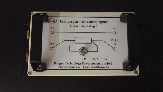
1.1. According to the IEC 61347-1:2012 standard, clause 14.6 a requires that the circuit be connected, as shown in figure (1) :
![]()
1.2 Adjust the oscilloscope input display ratio to X1, Y-axis adjustment to 1V/div, X-axis adjustment to 20mS/div, and the synchronization status is set to normal synchronization.
1.3 For example: connect the power supply, the oscilloscope waveform is the current of the test device, and the waveform is shown in figure 2.
![]()
Current reading method: peak voltage: 1.9V, peak current 190A (current to voltage ratio 100:1) RMS voltage: 1.34V, RMS current is 134A
According to the requirements of IEC 61347-1:2012, power supply and test equipment can be qualified to flow 160A +10% -0% current constantly.
2.1 According to IEC 61347-1:2012 standard, Clause 14.6-b connects the tested products, as shown in Figure below
![]()
3.1 According to IEC 61347-1:2012 standard, Clause 14.6-C, connect to the power supply for testing, oscilloscope setting method and current reading method is the same as 1.2,1.3.
Technical Parameters
1, working voltage: <1000Vac
2, working frequency: 50/60Hz
3, working current: <500Aac<500Aac
Note:
- Before the test, check whether the terminal fixing screws are tightened to ensure good contact.
- According to the standard "IEC61347-1:2012", confirm that the state is good at 160A +10% -0%, and the signal output is normal.
- poor contact or beyond the scope of use can cause damage to the test device.
![]()
![]()
![]()
![]()