


|
Detail Information |
|||
| Test Voltage:: | DC:0.5 - 2.5(kV) | Display Accuracy: | ±5% |
|---|---|---|---|
| Test Resistance: | 1 Kv-2.5kv 1 - 20000(MΩ)±5%, 0.5 Kv-1kv 1 - 10000(MΩ)±5% | Test Time: | 2 - 999.5 (S)±5% |
| Resolution: | 0.5(s) | Power Supply Voltage: | AC220V/50Hz |
| High Light: | MS2675DN-IID Insulation Resistance Tester,50Hz Insulation Resistance Tester,2.5kV Insulation Resistance Test Equipment |
||
Product Description
1. Product Overview
1.1 Product Profile
The MS2675DN-IID tester is an insulation resistance tester, it has 4 sets of memory modes with RS232 and PLC interfaces.
The test circuits provided by this tester meet the Household and Similar Electrical Appliances - Safety Part I General Requirements (GB4706.1), Testing Operational Procedure of Household and Similar Electrical Appliances Safety General Requirements (I) (GB5956), and the national testing standards for household appliances.
1.2 Applicable standards
GB4706.1, IEC60335-1, UL60335-1 Household and Similar Electrical Appliances - Safety Part I General Requirements;
GB4943,UL60950,IEC60950 Information Technology Equipment Safety;
GB8898,UL60065,IEC60065 Audio, Video and Similar Electronic Apparatus - Safety Requirements;
GB4793.1,IEC61010-1, Safety Requirements for Electrical Equipment for Measurement, Control and Laboratory Part I: General Requirements.
1.3 Application fields
1.3.1 Devices: diode, transistor, high voltage silicon stack, high voltage capacitor, electronic transformer, connector, low voltage electrical switch, AC contactor, etc.
1.3.2 Household appliances: TV set, refrigerator, air conditioner, washing machine, bread machine, kitchen treasure, electric water heater, electric blanket, charger, etc.
1.3.3 Instruments: oscilloscope, DC power supply, switching power supply, etc.
1.3.4 Office equipment: computer, printer, fax machine, telephone set, copier, money detector, etc.
1.3.5 Lighting appliances: ballast, road lamp, stage lamp, hand lamp, energy-saving lamp, etc.
1.3.6 Electric apparatus: electric drill, pistol drill, cutting machine, grinding machine, grinding machine, welding machine, etc.
1.3.7 Motor: rotating motor, small and special electric machine, motor, etc.
1.3.8 Insulation material: thermoplastic casing, capacitor film, high voltage casing, insulating paper, insulating shoes, insulating rubber gloves, PCB circuit board, etc.
1.3.9 Wire and cable: cable, optical cable, rubber cable, high voltage wire, etc.
1.4 Product characteristics
This series of tester uses the microprocessor as the core, which can complete each test accurately by the test channel collecting the parameter change of the tested appliance in real time.
The tester uses a backlight liquid crystal display screen, which has soft light, high definition, and small influence from environmental light; the double-entry menu is simple and easy to be understood; it can display test results in full screen; the multi-group test condition memory can easily realize the test of a variety of electrical appliances.
2 Main Technical Indicators and Parameters
Test voltage: DC:0.5 - 2.5(kV)
Display accuracy: ±5%
Test resistance: 1 kv-2.5kv 1 - 20000(MΩ)±5%
0.5 kv-1kv 1 - 10000(MΩ)±5%
Resolution: 01.000 - 10.000 (MΩ)
010.00 - 100.00 (MΩ)
0100.0 - 1000.0 (MΩ)
01000 - 20000 (MΩ)
Test time: 2 - 999.5 (S)±5%
Resolution: 0.5(s)
Power supply voltage: AC220V/50Hz
3. Main Functions
3.1 Safety protection functions
a. Shut off and alarm against short circuit.
b. Alarm against out of tolerance
3.2 Memory function
The tester can save the commonly used test mode. After the test is completed, the screen can keep the test data displayed.
3.3 Interface functionality (need to be booked before purchase)
a. It is equipped with 232 interfaces (it can be equipped with 232-485 converter): users can operate the instrument through the computer, to start, reset and read data.
b. It is equipped with a PLC interface.
-
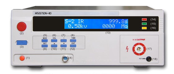
Instruction of Instrument Panel Structure
4.2 Introduction of all parts:
(1) Input power switch: Press down the switch to turn on the power supply and key up to turn off the power supply.
(2) “Start” key: it can be used as a test start switch
(3) “STOP” key: reset switch as switch alarm sound when tested. In the course of the test, it can also be used as a switch to interrupt the test. When setting mode can be used as a switch to exit setting mode.
(4) External control terminal (not supported by this instrument).
(5) “MOD” key: it is a mode key; it can save 4 modes with the preset test environment parameters saved in the mode.
(6) “VOL” key: it is a shortcut key for setting voltage values.
(7) “I” key: it is a shortcut key for setting resistance.
(8) “TIME” key: it is a shortcut key for setting test time.
(9) “SET” key: it is used as a set key.
(10) “∧” UP key: it is a function key for numeric input of each test parameter.
(11) “∨” DOWN key: it is a function key for numeric input of each test parameter.
(12) “ENT” key: it the key to enter set results.
(13) LCD: 20 × 2 line backlight LCD displayer; it is used to display setting data or test results.
(14) Indicator of test: press the start key, and this indicator lights up.
(15) Indicator of qualified test: if the test is qualified, this indicator lights up
(16) Indicator of alarm: this indicator lights up when the resistance exceeds the preset value.
(17) High voltage output terminal.
(18) Test terminal, high voltage loop terminal.
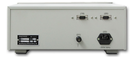
(19) “PLC” interface: It is a 9PIND terminal block containing the monitoring signal outputs of PROCESSING (in test), PASS (test passed), and FALL (test failure) and the remote-control signal inputs of TEST and RESET. The wiring is as follows:
PROCESSING output signal: between PIN1 and PIN4. (two points are conducted when the signal is available)
PASS output signal: between PIN6 and PIN7. (two points are conducted when the signal is available)
FALL output signal: between PIN8 and PIN9. (two points are conducted when the signal is available)
TEST input signal: between PIN2 and PIN5. (two points are conducted to control)
RESET input signal: between PIN3 and PIN5. (two points are conducted to control)
-
“232” interface: it is a standard 9 PIND terminal seat, with 232-485 converter, which can achieve 485 functions.
(21) Grounding terminal: it is used as safety protection of ground post.
(22) Input power outlet: It is a standard power jacket equipped with 5A fuses.
5 Introductions for Instrument Operation and Settings
5.1 Introductions of setting parameters and related interfaces
5.1.1 Figure 1 shows the interface after start up; press any key, you can enter the interface shown in Figure 2.
When the value bit (xxx) in the interface is K word, you should first press the UP key, hold the up and down key, the number can jump quickly.
|
|
|
|
|
|
|
W |
E |
L |
C |
O |
M |
E |
|
|
|
|
|
|
|
|
|
M |
i |
n |
s |
h |
e |
n |
g |
|
I |
n |
s |
t |
r |
u |
m |
e |
n |
t |
Figure 1
|
S |
-- |
x |
|
M |
|
|
|
2 |
|
I |
R |
|
|
|
|
|
|
|
|
|
|
x |
x |
. |
x |
S |
|
|
|
|
|
|
|
|
|
x |
x |
H |
z |
|
Figure 2
5.1.2 Press “SET” key, and choose the items that need to be set in turn as the cursor moves. You can also press the shortcut key “MOD”, “VOL”, “I”, and “TIME” to set. As shown in Figure 5, Figure 6, and Figure 7, press the “↑”, “↓” key to change the data.
Figure 3 shows setting the test mode (1-4).
Figure 5 shows setting the test time.
Figure 6 shows setting the output voltage value.
Figure 7 shows setting the lower limit of the set resistance.
After setting, press “ENT” key to save the settings and exit back to the interface in Figure 8.
5.1.3 As shown in the cursor in Figure 3, press the mode key “MOD” repeatedly to select the number of modes, as shown in Figure 3. This is mode 1, and continue to press the “MOD” key to cycle and select within modes 1-4.
|
S |
-- |
1 |
|
M |
|
|
|
|
2 |
|
I |
R |
|
|
|
|
|
|
|
|
|
x |
x |
. |
x |
S |
|
|
|
|
|
|
|
|
|
x |
x |
H |
z |
|
Figure 3
5.1.4 Press “SET” key to enter the interface shown in Figure 4; press “SET” key again, as the cursor in Figure 5 shown, and press UP and DOWN keys to change the value. The insulation test time is 50 S.
|
S |
-- |
1 |
|
I |
R |
|
|
|
|
|
|
|
|
x |
x |
x |
. |
x |
S |
|
|
x |
. |
x |
x |
k |
v |
|
|
|
|
|
|
x |
x |
x |
x |
|
M |
Ω |
Figure 4
|
S |
-- |
1 |
|
I |
R |
|
|
|
|
|
|
|
|
0 |
5 |
0 |
. |
0 |
S |
|
|
x |
. |
x |
x |
k |
v |
|
|
|
|
|
|
x |
x |
x |
x |
|
M |
Ω |
Figure 5
5.1.5 Press the “SET” key again, as the cursor in Figure 9 shown; press UP and DOWN key to change the value; the insulation output voltage value is 500 V.
|
S |
-- |
1 |
|
I |
R |
|
|
|
|
|
|
|
|
0 |
5 |
0 |
. |
0 |
S |
|
|
0 |
. |
5 |
0 |
k |
v |
|
|
|
|
|
|
x |
x |
x |
x |
|
M |
Ω |
Figure 6
5.1.6 Press the “SET” key again, as the cursor in Figure 10 shown; press the UP and DOWN keys to change the value; the insulation resistance limit is 500 MΩ
|
S |
-- |
1 |
|
I |
R |
|
|
|
|
|
|
|
|
0 |
5 |
0 |
. |
0 |
S |
|
|
0 |
. |
5 |
0 |
k |
v |
|
|
|
|
|
|
0 |
5 |
0 |
0 |
|
M |
Ω |
Figure 7
5.1.7 Press “ENT” key to save settings and exit, as shown in Figure 11; press “ENT” key again to enter the interface shown in Figure 8; wait for test.
|
S |
-- |
1 |
|
I |
R |
|
|
|
|
|
|
|
|
0 |
5 |
0 |
. |
0 |
S |
|
|
0 |
. |
5 |
0 |
k |
v |
|
|
|
|
|
|
0 |
5 |
0 |
0 |
|
M |
Ω |
Figure 8