


 |
ANSI/AAMI EC12:2000(R2005) Disposable ECG Electrode Performance Tester
Product Details:
| Place of Origin: | China |
| Brand Name: | Kingpo |
| Certification: | Calibration Certificate |
| Model Number: | ECG101 |
Payment & Shipping Terms:
| Minimum Order Quantity: | 1 |
|---|---|
| Price: | To be quoted |
| Packaging Details: | safety carton pack or plywood box |
| Delivery Time: | 15 working days |
| Payment Terms: | T/T |
| Supply Ability: | 50 pcs/ month |
|
Detail Information |
|||
| High Light: | ECG Electrode Performance Tester,lectrode Performance Tester Instrument,220V 50H Electrode Performance Tester |
||
|---|---|---|---|
Product Description
ANSI/AAMI EC12:2000(R2005) Disposable ECG Electrode Performance Tester
Notes
-
This instrument uses AC 220V /50H z, to prevent failure or damage, use the tester within the specified voltage range.
-
To ensure safety, ensure that the ground wire in the instrument power cord is reliably grounded; yes
-
Always remove the power plug when replacing the fuse.
-
In an emergency (the occurrence of electric shock accident), the following operation must be taken: Turn off the power switch of the instrument and remove the power cord of the instrument from the power outlet.
-
The instrument is not suitable for a long time. Store it in the original packaging box or similar box in a ventilation room with a temperature of 5℃ ~40℃ and relative humidity not more than 85%RH. The air shall not contain harmful impurities of the corrosive tester, and direct sunlight shall be avoided.
-
Please do not use it in bad environments, including dust, vibration, direct sunlight and corrosive gas.
-
Brief Introduction
This equipment is a specialized equipment for electrode integrated performance testing, designed under the Test Method of disposable ECG electrode ANSI/AAMI EC12:2000(R2005) Disposable ECG electrodes>. Its main characteristics are built-in standard test program that can automatically complete the performance tests of the electrode with one button; built-in test circuit without additional tooling; automatically produce data results.
The following test procedures are built-in for this equipment:
-
AC impedance test.
-
DC imbalance voltage test.
-
Composite disorder instability and internal noise testing.
-
Defibrillation overload recovery test.
-
Offset current tolerance test.
Performance parameters
Table 3.1 Performance parameters
|
Signal source
|
|||
|
Name
|
Signal type
|
Output range
|
Frequency range
|
|
Microsafe current source
|
Sine-idal wave
|
0~220uA /5V
|
1~100Hz
|
|
Naan current source
|
DC current
|
0~300nA
|
D C
|
|
Defibrillation voltage source
|
DC current
|
100~250V
|
D C
|
|
Voltmeter
|
|||
|
Name
|
Signal type
|
Enter the range.
|
|
|
5mV voltmeter.
|
AC / DC current.
|
-5~5mV
|
0~1KHz
|
|
The 400mV voltmeter.
|
AC / DC current.
|
-400~400mV
|
0~1KHz
|
|
5V voltmeter.
|
AC / DC current
|
-5~5V
|
0~1KHz
|
|
The 300V voltmeter
|
DC current
|
0~250V
|
D C
|
|
Screen
|
|||
|
Dimensions
|
Touch function
|
Resolution
|
Display the scale
|
|
About 7 inches
|
Capacitive induction type
|
1026×600
|
16:9
|
|
Power supply
|
|||
|
Voltage
|
Frequency
|
Power supply
|
|
|
220V±10V
|
50Hz
|
Max. 35VA.
|
|
|
Size and weight.
|
|||
|
Long × wide × high.
|
Weight.
|
||
|
454mm ×356mm ×165mm
|
15Kg
|
||
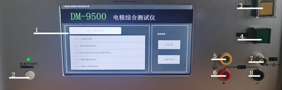
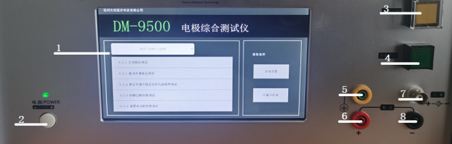
Instrument introduction.
① Touch display: functional display area, touch can achieve all functional human-machine interaction.
② power switch button: press the instrument to power on
③ Defibrillation control button: During the defibrillation overload recovery test, press this button to start the test
④ Start / Stop Button: At the test interface, press this button to control the start and stop of the test
⑤ protective grounding end: for connecting the shield metal housing.When making weak signal measurement such as noise, if the environmental noise is found large, the D UT can be protected with a metal shield and the shield connected to the ground, allowing the limited shielding of external electromagnetic radiation.
Positive pole of ⑥ output: Current output positive pole terminal.
Negative pole of ⑦ output: current output negative terminal terminal.
⑧ voltage measurement end: the terminal used for measuring the voltage
Operation method
-
Software home page
Figure 5.1.1 The Main Software Page
l. Default enters the main page after the instrument is turned on The model and name of the instrument are displayed at the top, the basic function of the instrument on the lower left, and the advanced options on the lower right
2. Tests for different items can be selected directly through the directory at the lower left To system the device or calibration, you can enter the setup interface by clicking the bottom right
Typical test circuit
Voltage measuring end
Figure 5.1.2 Test the circuit
-
AC impedance test
Figure 5.2 The AC Impedance Test Page.
l The AC impedance test page mainly sets the current source and voltmeter parameters for the test, and displays the measured AC impedance and peak value voltage. You can also choose whether to record or empty the data, and control the start and stop of the test.
2 The AC impedance of the cardiac electrode reflects the ability to prevent the current from flowing through the electrode interface and the electrode interface.
3 The impedance of a pair of glue to glue connections can be determined by applying a sinusoidal wave current with a known amplitude and observing the voltage amplitude of the electrode to both ends The magnitude of the impedance is the ratio of the voltage to the current The peak value of the applied current shall not exceed 100u A.
-
DC imbalance voltage test.
Figure 5.3 The DC imbalance voltage test page.
l The DC imbalance voltage test page mainly sets the current source and voltmeter parameters for the test, and displays the test time and measured voltage. You can also choose whether to record or empty the data, and control the start and stop of the test
2 The DC imbalance voltage is a voltage formed between the adhesive bonding electrode pairs due to a different electrode semi-battery potential.
3 The test instrument is applied to the bias current of the test electrode no more than 10nA, and is measured by the voltmeter at the ends after 1min and 1.5min. The abnormal voltage shall be no greater than 100mV..
-
Composite disorder instability and internal noise testing.
Figure 5.4 Composite disorder instability and internal noise test page.
l The composite disorder instability and internal noise test page mainly sets the voltmeter parameters for the test, and displays the test time and measured peak voltage. You can also choose whether to record or empty the data, and control the start and stop of the test.
2 The voltage generated by a pair of glue-connected electrode pairs at 1min under a frequency band of 0.15Hz ~100H z is directly measured by a voltmeter. The peak voltage of subsequent 5min shall not exceed 150u V..
-
Defibrillation overload recovery test
Figure 5.5 The Defibrillation Overload Recovery test page
l The defibrillation overload recovery test page mainly sets the defibrillation voltmeter, ammeter and voltmeter parameters for the test, and displays the test time, measured voltage and measured AC impedance. Data in the test is recorded automatically recorded, you can choose whether to record or empty data, and control the start and stop of the test.
2 The defibrillation overload recovery experiment reflects the ability of the electrode to reduce its existing voltage and restore the ECG description after defibrillation.
3 Press the defibrillation control button and start the key instrument to start the test, and the test results are automatically displayed on the page.
4 The 10 uF capacitor charged to 200V is discharged through a series circuit of the electrode to 100 Ω resistance, the absolute value of the polarization electric potential of the electrode pair after the capacitor starts discharge does not exceed 100m V. within then 30s and the rate of change of the remaining polarization electric potential is not greater than ± 1m V/s. After the above experiment, the 10Hz AC impedance of the electrode pair shall be no greater than 3kΩ.
-
Offset current tolerance test
Figure 5.6 Offset current tolerance test page
l The bias current tolerance test page mainly sets the current source and voltmeter parameters for the test, and displays the test time and measured voltage. You can also choose whether to record or empty the data, and control the start and stop of the test. You can also choose whether to record the data automatically.
2 This test verifies the compatibility of the electrode with the 200nA bias current allowed by the cardiac monitor.
3 A 200n A DC current is applied to a pair of adhesive electrodes, which monitors a voltmeter at both ends. The change in voltage on the electrode is measured at least once an hour.
4 The voltage variation of the electrodes observed over the entire duration shall not be greater than 100mV. The duration is the electrode clinical usage recommended by the manufacturer and in no case shall it be less than 8h.
-
Measurement and calibration
Figure 5.7 Measurement and calibration page
l The operation of the defibrillation power supply will output a high voltage of 200V, which may damage the voltage measurement channel, so only used by after-sales personnel of the manufacturer.
2 Defibrillation voltage measurement method:
-
Go to the Defibrillation Overload Recovery Test page.
n The positive and negative output of the instrument are connected to the positive and negative poles of the oscilloscope probe, without the load.
n Set the defibrillation voltage of 200 V, and start the defibrillation test.
-
Use the external oscilloscope to see if the defibrillator power supply reaches 200V.
l Measurement method of the current source:
-
The AC current source 100uA test circuit is shown in 5.1.2, and the D TU is replaced with a standard resistance of 10KΩ.You need to verify that the peak value of 100uA is the AC power supply, and you can measure the effective value of the AC power source with the multimeter, or view the peak value with the oscilloscope. The measured effective value needs to be converted to a peak value by 2.828. In addition, pay attention to the impact of the input impedance of the multimeter or oscilloscope on the test circuit. It is recommended to choose a voltage measuring device with an input impedance that is greater than 1G Ω.
-
The DC current source 100nA test circuit is shown in 5.1.2.The D TU is replaced with a 10KΩ standard resistance, and the voltmeter input impedance used for all measurements is greater than 10GΩ.
-
Voltage measurement measurement method:
The appropriate voltage is input at the voltage measuring end, the input voltage value is measured in three gears of the voltmeter, and compares the test value relative to the actual voltage value to determine the accuracy of the voltmeter.
Common faults and troubleshooting
|
No ial
|
Faault
|
Inspection and exclusion methods
|
|
1
|
The measurement data appears as zero
|
The voltmeter range is too small, stop testing to select a large range of voltmeter retesting.
|
|
2
|
Adjust the current source and voltmeter setting measurement unchanged
|
The current source and voltmeter parameters shall be adjusted under the test and readjust parameters for test.
|
|
3
|
The measurement noise is too large
|
|
Want to Know more details about this product