|
|
| MOQ: | 1 |
| Price: | To be quoted |
| Standard Packaging: | plywood box |
| Delivery Period: | 30 working days |
| Payment Method: | T/T |
| Supply Capacity: | 2 units per month |
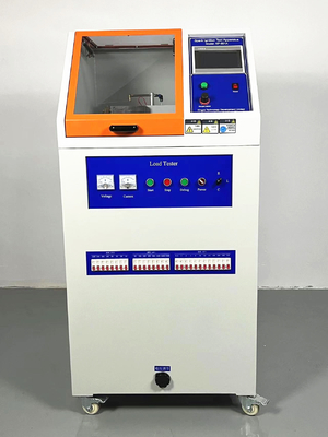
IEC 60601-1 Spark Ignition Tester to check the RISK of fire in an OXYGEN RICH ENVIRONMENT for ME EQUIPMENT & ME SYSTEMS
1.According to standard:
IEC 60601-1-Figure 34-figure37(clause 11.2.2)
2.Specifications
| Power Supply | AC220V 50HZ |
| According to the standard: | IEC 60601-1-Figure 34-37 |
| Test speed: | 0-30 times/min (PLC control) |
| Test times: | 0-99999 can be set |
| Oxygen speed: | less than 0.5m/s,(can be set) |
| Maximum output voltage (DC): | 0-80V |
| Maximum current output (DC): | 2A |
| weight and dimension: | 150kg , 850*900*1650mm(w*d*h) |
11.2.2 M E EQUIPMENT and ME SYSTEMS used in conjunction with OXYGEN RICH ENVIRONMENT
11.2.2.1 RISK of fire in an OXYGEN RICH ENVIRONMENT
In ME EQUIPMENT and ME SYSTEMS , the RISK of fire in an OXYGEN RICH ENVIRONMENT shall be reduced as far as possible under NORMAL CONDITION or SINGLE FAULT CONDITIONS (as identified in 11 .2.3). An unacceptable RISK of fire is considered to exist in an OXYGEN RICH ENVIRONMENT when a source of ignition is in contact with ignitable material and there is no means that would limit the spread of a fire.
NOTE 1 For oxygen concentrations up to 25 % at one atmosphere or partial pressures up to 27,5 kPa for higher atmospheric pressures, the requirements in 1 3.1 .1 are considered to be sufficient.
a) * A source of ignition is considered to exist in an OXYGEN RICH ENVIRONMENT when any of the following conditions exist in NORMAL CONDITION and SINGLE FAULT CONDITIONS (including voltage and current):
1 ) the temperature of the material is raised to its ignition temperature;
2) temperatures could affect solder or solder joints causing loosening, short circuiting or other failures that could result in sparking or raising the temperature of the material to its ignition temperature;
3) parts affecting safety crack or change their outer shape exposing emperatures exceeding 300 °C or sparks (see 4) and 5) below) due to overheating;
4) temperatures of parts or components could exceed 300 °C;
5) sparks provide adequate energy for ignition by exceeding the limits of Figure 35 to Figure 37 (inclusive).
Items 4) and 5) address the worst case where the atmosphere is 1 00 % oxygen, the contact material (for item 5) is solder and the fuel is cotton. Available fuels and oxygen concentrations should be taken into consideration when applying these specific requirements. Where deviations from these worst case limits are made (based on lower oxygen concentrations or less flammable fuels) they shall be justified and documented in
the RISK MANAGEMENT FILE .
As an alternative to 11.2.2.1 a) 5), the following test may be used to determine whether a source of ignition exists.
First, the place(s) within the ME EQUIPMENT where sparking might cause ignition are identified. Then the material(s) of the parts between which sparks can occur is identified.
Samples of the same material are then used to construct the contact pins for the test apparatus (see Figure 34).
Other parameters for the test are: oxygen concentration, fuel, electrical parameters (current, voltage, capacitance, inductance or resistance). These parameters are chosen such that they represent the worst case for the ME EQUIPMENT
Two contact pins made of the material to be considered are placed in opposition (see Figure 34). One pin has a diameter of 1 mm, the other of 3 mm. The electrical source is connected to the pins as shown in Figure 35 to Figure 37. A piece of cotton is placed close to the contact surfaces of the two pins. The contacts are constantly flushed by oxygen with a speed of less than 0,5 m/s via a tube. The cathode is moved to the anode to close the contacts and pulled back to open them again. A minimum of 300 trials has to be performed before it can be decided that the sparks do not ignite. If the sparks get smaller because of bad surfaces of the electrodes, the electrodes are cleaned with a file. If the cotton gets
black because it became oxidized then it is replaced. In Figure 36 and Figure 37, the resistance used to control current flowing into the inductor and the time constant for charging the capacitor is chosen such that it has minimal impact on the energy of the spark. This is tested by visual inspection without the capacitor in place or with the inductor shorted.
The situation with the highest voltage or current respectively and no ignition defines the upper limit. A safe upper limit is given by dividing the upper limit of voltage or current respectively with the safety margin factor of three.
Figure 34 – Spark ignition test apparatus
![]()
Figure 35 – Maximum allowable current I as a function of the maximum allowable voltage U measured in a purely resistive circuit in an OXYGEN RICH ENVIRONMENT
![]()
Figure 36 – Maximum allowable voltage U as a function of the capacitance C measured in a capacitive circuit used in an OXYGEN RICH ENVIRONMENT
![]()
Figure 37 – Maximum allowable current I as a function of the inductance L measured in an inductive circuit in an OXYGEN RICH ENVIRONMENT
![]()

|
|
| MOQ: | 1 |
| Price: | To be quoted |
| Standard Packaging: | plywood box |
| Delivery Period: | 30 working days |
| Payment Method: | T/T |
| Supply Capacity: | 2 units per month |
IEC 60601-1 Spark Ignition Tester to check the RISK of fire in an OXYGEN RICH ENVIRONMENT for ME EQUIPMENT & ME SYSTEMS
1.According to standard:
IEC 60601-1-Figure 34-figure37(clause 11.2.2)
2.Specifications
| Power Supply | AC220V 50HZ |
| According to the standard: | IEC 60601-1-Figure 34-37 |
| Test speed: | 0-30 times/min (PLC control) |
| Test times: | 0-99999 can be set |
| Oxygen speed: | less than 0.5m/s,(can be set) |
| Maximum output voltage (DC): | 0-80V |
| Maximum current output (DC): | 2A |
| weight and dimension: | 150kg , 850*900*1650mm(w*d*h) |
11.2.2 M E EQUIPMENT and ME SYSTEMS used in conjunction with OXYGEN RICH ENVIRONMENT
11.2.2.1 RISK of fire in an OXYGEN RICH ENVIRONMENT
In ME EQUIPMENT and ME SYSTEMS , the RISK of fire in an OXYGEN RICH ENVIRONMENT shall be reduced as far as possible under NORMAL CONDITION or SINGLE FAULT CONDITIONS (as identified in 11 .2.3). An unacceptable RISK of fire is considered to exist in an OXYGEN RICH ENVIRONMENT when a source of ignition is in contact with ignitable material and there is no means that would limit the spread of a fire.
NOTE 1 For oxygen concentrations up to 25 % at one atmosphere or partial pressures up to 27,5 kPa for higher atmospheric pressures, the requirements in 1 3.1 .1 are considered to be sufficient.
a) * A source of ignition is considered to exist in an OXYGEN RICH ENVIRONMENT when any of the following conditions exist in NORMAL CONDITION and SINGLE FAULT CONDITIONS (including voltage and current):
1 ) the temperature of the material is raised to its ignition temperature;
2) temperatures could affect solder or solder joints causing loosening, short circuiting or other failures that could result in sparking or raising the temperature of the material to its ignition temperature;
3) parts affecting safety crack or change their outer shape exposing emperatures exceeding 300 °C or sparks (see 4) and 5) below) due to overheating;
4) temperatures of parts or components could exceed 300 °C;
5) sparks provide adequate energy for ignition by exceeding the limits of Figure 35 to Figure 37 (inclusive).
Items 4) and 5) address the worst case where the atmosphere is 1 00 % oxygen, the contact material (for item 5) is solder and the fuel is cotton. Available fuels and oxygen concentrations should be taken into consideration when applying these specific requirements. Where deviations from these worst case limits are made (based on lower oxygen concentrations or less flammable fuels) they shall be justified and documented in
the RISK MANAGEMENT FILE .
As an alternative to 11.2.2.1 a) 5), the following test may be used to determine whether a source of ignition exists.
First, the place(s) within the ME EQUIPMENT where sparking might cause ignition are identified. Then the material(s) of the parts between which sparks can occur is identified.
Samples of the same material are then used to construct the contact pins for the test apparatus (see Figure 34).
Other parameters for the test are: oxygen concentration, fuel, electrical parameters (current, voltage, capacitance, inductance or resistance). These parameters are chosen such that they represent the worst case for the ME EQUIPMENT
Two contact pins made of the material to be considered are placed in opposition (see Figure 34). One pin has a diameter of 1 mm, the other of 3 mm. The electrical source is connected to the pins as shown in Figure 35 to Figure 37. A piece of cotton is placed close to the contact surfaces of the two pins. The contacts are constantly flushed by oxygen with a speed of less than 0,5 m/s via a tube. The cathode is moved to the anode to close the contacts and pulled back to open them again. A minimum of 300 trials has to be performed before it can be decided that the sparks do not ignite. If the sparks get smaller because of bad surfaces of the electrodes, the electrodes are cleaned with a file. If the cotton gets
black because it became oxidized then it is replaced. In Figure 36 and Figure 37, the resistance used to control current flowing into the inductor and the time constant for charging the capacitor is chosen such that it has minimal impact on the energy of the spark. This is tested by visual inspection without the capacitor in place or with the inductor shorted.
The situation with the highest voltage or current respectively and no ignition defines the upper limit. A safe upper limit is given by dividing the upper limit of voltage or current respectively with the safety margin factor of three.
Figure 34 – Spark ignition test apparatus
![]()
Figure 35 – Maximum allowable current I as a function of the maximum allowable voltage U measured in a purely resistive circuit in an OXYGEN RICH ENVIRONMENT
![]()
Figure 36 – Maximum allowable voltage U as a function of the capacitance C measured in a capacitive circuit used in an OXYGEN RICH ENVIRONMENT
![]()
Figure 37 – Maximum allowable current I as a function of the inductance L measured in an inductive circuit in an OXYGEN RICH ENVIRONMENT
![]()
address
RM C, 13/F, HARVARD COMMERCIAL BUILDING, 105-111 THOMSON ROAD, WAN CHAI, HK
tel
86-769- 81627526