|
|
| MOQ: | 1 |
| Price: | To be Quoted |
| Standard Packaging: | safety tool box or plywood pack. |
| Delivery Period: | 25 working days |
| Payment Method: | T/T |
| Supply Capacity: | 25 sets per month |
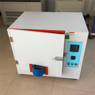
IEC 61347-1 Annex D Test Chamber / heating enclosure for thermally protected ballasts / Rectifier thermal protection
D.1 Test enclosure
The heating tests are made in an enclosure in which the temperature of the ambient air is
maintained as specified (see Figure D.1). The entire test enclosure shall be constructed of
heat resistant material 25 mm thick. The test compartment of this enclosure shall have
internal dimensions of 610 mm × 610 mm × 610 mm. The floor of the test compartment shall measure 560 mm × 560 mm, permitting an air space of 25 mm all around the platform for circulation of the heated air. A 75 mm heater compartment shall be provided below the floor of the test area for the heating elements. One side of the test compartment may be removable,
but shall be so constructed that it can be securely fastened to the remainder of the enclosure.
One of the sides shall have a 150 mm square opening located centrally at the bottom edge of
the test compartment, and the enclosure so constructed that the only possibility of air
circulation will be through this opening. The opening shall be covered by an aluminium shield
as shown in Figure D.1.
D.2 Heating of enclosure
The heat source used for the test enclosure described above shall consist of four 300 W strip
heaters having approximate heating surface dimensions of 40 mm × 300 mm. These elements shall be connected in parallel to the supply source. The elements shall be mounted in the 75 mm heater compartment midway between the test compartment floor and the base, and so arranged that they form a square with the outside edge of each element 65 mm from the adjacent inside wall of the enclosure. The elements shall be controlled by a suitable thermostat.
D.3 Lamp controlgear operating conditions
During the test, the frequency of the supply circuit shall be the rated frequency of the lamp
controlgear, and the voltage of the supply circuit shall be the rated supply voltage of the lamp
controlgear. During the test, the temperature in the enclosure shall be maintained at 0
40(+0,-5) °C; prior to the test, the lamp controlgear (not energized) shall be placed in the chamber for a sufficient interval of time to allow all parts to attain the temperature of the air therein. If the temperature in the chamber at the end of the test differs from that at the beginning of the test,this temperature differential shall be taken into account in determining the temperature rise of the components of the lamp controlgear. The lamp controlgear shall supply the number and size of lamps for which it is intended. Lamps shall be placed outside the enclosure.
D.4 Lamp controlgear position in the enclosure
During the test, the lamp controlgear shall be in its normal operating position supported
75 mm above the floor of the test compartment by two 75 mm wooden blocks, and shall be
centrally located with respect to the sides of the enclosure. Electrical connections may be
brought out of the enclosure through the 150 mm square opening illustrated in Figure D.1.
During the test, the enclosure shall be so located that the shielded opening is not exposed to
draughts or rapid air currents
D.5 Temperature measurements
The average ambient temperature in the enclosure is assumed to be the average air
temperature at positions not less than 76 mm from the nearest wall and on a level with the
centre of the lamp controlgear.
The temperature is usually measured by a glass thermometer. An alternative sensor is a
thermocouple or 'thermistor' attached to a small metal vane shielded against radiation.
Temperatures on the case are usually measured by means of thermocouples. A temperature
is considered to be constant when three successive readings, taken at intervals of 10 % of the
previously elapsed duration of the test (but not less than 5 min intervals), indicate no change.
![]()

|
|
| MOQ: | 1 |
| Price: | To be Quoted |
| Standard Packaging: | safety tool box or plywood pack. |
| Delivery Period: | 25 working days |
| Payment Method: | T/T |
| Supply Capacity: | 25 sets per month |
IEC 61347-1 Annex D Test Chamber / heating enclosure for thermally protected ballasts / Rectifier thermal protection
D.1 Test enclosure
The heating tests are made in an enclosure in which the temperature of the ambient air is
maintained as specified (see Figure D.1). The entire test enclosure shall be constructed of
heat resistant material 25 mm thick. The test compartment of this enclosure shall have
internal dimensions of 610 mm × 610 mm × 610 mm. The floor of the test compartment shall measure 560 mm × 560 mm, permitting an air space of 25 mm all around the platform for circulation of the heated air. A 75 mm heater compartment shall be provided below the floor of the test area for the heating elements. One side of the test compartment may be removable,
but shall be so constructed that it can be securely fastened to the remainder of the enclosure.
One of the sides shall have a 150 mm square opening located centrally at the bottom edge of
the test compartment, and the enclosure so constructed that the only possibility of air
circulation will be through this opening. The opening shall be covered by an aluminium shield
as shown in Figure D.1.
D.2 Heating of enclosure
The heat source used for the test enclosure described above shall consist of four 300 W strip
heaters having approximate heating surface dimensions of 40 mm × 300 mm. These elements shall be connected in parallel to the supply source. The elements shall be mounted in the 75 mm heater compartment midway between the test compartment floor and the base, and so arranged that they form a square with the outside edge of each element 65 mm from the adjacent inside wall of the enclosure. The elements shall be controlled by a suitable thermostat.
D.3 Lamp controlgear operating conditions
During the test, the frequency of the supply circuit shall be the rated frequency of the lamp
controlgear, and the voltage of the supply circuit shall be the rated supply voltage of the lamp
controlgear. During the test, the temperature in the enclosure shall be maintained at 0
40(+0,-5) °C; prior to the test, the lamp controlgear (not energized) shall be placed in the chamber for a sufficient interval of time to allow all parts to attain the temperature of the air therein. If the temperature in the chamber at the end of the test differs from that at the beginning of the test,this temperature differential shall be taken into account in determining the temperature rise of the components of the lamp controlgear. The lamp controlgear shall supply the number and size of lamps for which it is intended. Lamps shall be placed outside the enclosure.
D.4 Lamp controlgear position in the enclosure
During the test, the lamp controlgear shall be in its normal operating position supported
75 mm above the floor of the test compartment by two 75 mm wooden blocks, and shall be
centrally located with respect to the sides of the enclosure. Electrical connections may be
brought out of the enclosure through the 150 mm square opening illustrated in Figure D.1.
During the test, the enclosure shall be so located that the shielded opening is not exposed to
draughts or rapid air currents
D.5 Temperature measurements
The average ambient temperature in the enclosure is assumed to be the average air
temperature at positions not less than 76 mm from the nearest wall and on a level with the
centre of the lamp controlgear.
The temperature is usually measured by a glass thermometer. An alternative sensor is a
thermocouple or 'thermistor' attached to a small metal vane shielded against radiation.
Temperatures on the case are usually measured by means of thermocouples. A temperature
is considered to be constant when three successive readings, taken at intervals of 10 % of the
previously elapsed duration of the test (but not less than 5 min intervals), indicate no change.
![]()
address
RM C, 13/F, HARVARD COMMERCIAL BUILDING, 105-111 THOMSON ROAD, WAN CHAI, HK
tel
86-769- 81627526