|
| MOQ: | 1 |
| Price: | 70USD/pcs |
| Standard Packaging: | safety carton pack or plywood box |
| Delivery Period: | 7 working days |
| Payment Method: | T/T |
| Supply Capacity: | 50 pcs per month |
Annex G
Measurement of touch current and protective conductor current
G.1 The luminaire is tested at an ambient temperature of 25 °C ± 5 °C and at rated supply voltage and frequency in the test circuit shown in Figure G.1.
G.2 The luminaire is operated with the lamp(s) of the type for which it is intended, such that,when stabilized at rated voltage, the lamp wattage and voltage of fluorescent and other discharge lamps are within ± 5 % of the rated values.
G.3 The protective conductor current is measured with the luminaire connected as described in 12.4.1. In addition, the measuring network in Figure G.4, with A and B connected in Figure G.1 between the PE conductor of the luminaire and the earth connection is used. The measuring network for touch current is disconnected.
The test sequence shall be as detailed in Clause G.5 but “e” always open and no measurements shall be made on class II luminaires.
The voltage U 4 measured with a high resistance voltmeter (electronic or an oscilloscope) in r.m.s. is divided by the resistor R and the value for the current is given in r.m.s.
G.4 For the measurements of the touch current, the circuit specified in Figures G.1, G.2, and G.3 are used.
The test sequence shall be as detailed in Clause G.5. The standard test finger in accordance with IEC 60529 is used as the test probe and is applied to accessible metal parts, or accessible insulating parts wrapped in foil, 10 cm x 20 cm in size, of the luminaire body.
The method of measurement described here is based on the assumption that the luminaire is used in a star TN or TT system, i.e. the luminaire is connected between line (L) and neutral (N). For other systems, see relevant clauses of the IEC 60990.
In case of multi phase connections, the same procedure occurs, but the measurements are made on one phase at the time. The same limits apply for each phase.
Measuring network of Figure G.3 is used for portable class I luminaires, while the measuring network of Figure G.2 is used in all other cases except when the protective conductor current is asked for.
The voltage U 2 and U 3 in the measuring networks of Figure G.2 and G.3 are peak voltages.
If frequencies above 30 kHz are involved, measurement of touch current shall include measurement with regard to electric burn effects in addition to measurement of Figure G.2. For the burn effects, the unweighted r.m.s. value of the touch-current is relevant. Unweighted touch-current is calculated from the r.m.s. voltage U 1 , measured across the 500 Ω resistor of Figure G.2.
The terminal A electrode (standard test finger) shall be applied to each accessible part in turn.
For each application of the terminal A electrode, the terminal B electrode shall be applied to earth, then applied to each of the other accessible parts in turn.
For measurement on class II luminaires, the protective conductor is ignored.
The test circuit of Figure G.1 shall employ an isolating transformer.
NOTE Requirements for class III luminaires, tracks and wire systems are under consideration.
G.5 Test sequence
The touch-current is measured as follows:
![]()
Figure G.1 – Test configuration: single-phase equipment on star TN or TT system
![]()
![]()
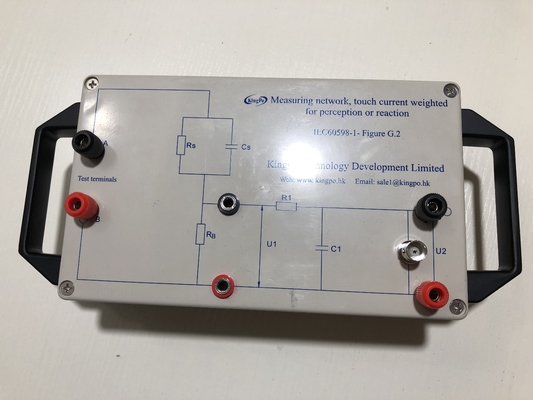
Figure G.2 – Measuring network, touch current weighted for perception or reaction (for all class II and fixed class I luminaires)
![]()
Figure G.3 – Measuring network, touch current weighted for let-go
(for portable class I luminaires)
![]()
![]()
![]()
Figure G.4 – Measuring network, weighted for high frequency protective conductor currents

|
|
| MOQ: | 1 |
| Price: | 70USD/pcs |
| Standard Packaging: | safety carton pack or plywood box |
| Delivery Period: | 7 working days |
| Payment Method: | T/T |
| Supply Capacity: | 50 pcs per month |
Annex G
Measurement of touch current and protective conductor current
G.1 The luminaire is tested at an ambient temperature of 25 °C ± 5 °C and at rated supply voltage and frequency in the test circuit shown in Figure G.1.
G.2 The luminaire is operated with the lamp(s) of the type for which it is intended, such that,when stabilized at rated voltage, the lamp wattage and voltage of fluorescent and other discharge lamps are within ± 5 % of the rated values.
G.3 The protective conductor current is measured with the luminaire connected as described in 12.4.1. In addition, the measuring network in Figure G.4, with A and B connected in Figure G.1 between the PE conductor of the luminaire and the earth connection is used. The measuring network for touch current is disconnected.
The test sequence shall be as detailed in Clause G.5 but “e” always open and no measurements shall be made on class II luminaires.
The voltage U 4 measured with a high resistance voltmeter (electronic or an oscilloscope) in r.m.s. is divided by the resistor R and the value for the current is given in r.m.s.
G.4 For the measurements of the touch current, the circuit specified in Figures G.1, G.2, and G.3 are used.
The test sequence shall be as detailed in Clause G.5. The standard test finger in accordance with IEC 60529 is used as the test probe and is applied to accessible metal parts, or accessible insulating parts wrapped in foil, 10 cm x 20 cm in size, of the luminaire body.
The method of measurement described here is based on the assumption that the luminaire is used in a star TN or TT system, i.e. the luminaire is connected between line (L) and neutral (N). For other systems, see relevant clauses of the IEC 60990.
In case of multi phase connections, the same procedure occurs, but the measurements are made on one phase at the time. The same limits apply for each phase.
Measuring network of Figure G.3 is used for portable class I luminaires, while the measuring network of Figure G.2 is used in all other cases except when the protective conductor current is asked for.
The voltage U 2 and U 3 in the measuring networks of Figure G.2 and G.3 are peak voltages.
If frequencies above 30 kHz are involved, measurement of touch current shall include measurement with regard to electric burn effects in addition to measurement of Figure G.2. For the burn effects, the unweighted r.m.s. value of the touch-current is relevant. Unweighted touch-current is calculated from the r.m.s. voltage U 1 , measured across the 500 Ω resistor of Figure G.2.
The terminal A electrode (standard test finger) shall be applied to each accessible part in turn.
For each application of the terminal A electrode, the terminal B electrode shall be applied to earth, then applied to each of the other accessible parts in turn.
For measurement on class II luminaires, the protective conductor is ignored.
The test circuit of Figure G.1 shall employ an isolating transformer.
NOTE Requirements for class III luminaires, tracks and wire systems are under consideration.
G.5 Test sequence
The touch-current is measured as follows:
![]()
Figure G.1 – Test configuration: single-phase equipment on star TN or TT system
![]()
![]()
Figure G.2 – Measuring network, touch current weighted for perception or reaction (for all class II and fixed class I luminaires)
![]()
Figure G.3 – Measuring network, touch current weighted for let-go
(for portable class I luminaires)
![]()
![]()
![]()
Figure G.4 – Measuring network, weighted for high frequency protective conductor currents
address
RM C, 13/F, HARVARD COMMERCIAL BUILDING, 105-111 THOMSON ROAD, WAN CHAI, HK
tel
86-769- 81627526