
|
| MOQ: | 1 |
| Price: | To be quoted |
| Standard Packaging: | safety carton pack or plywood box |
| Delivery Period: | 20 working days |
| Payment Method: | T/T |
| Supply Capacity: | 1000 pcs |
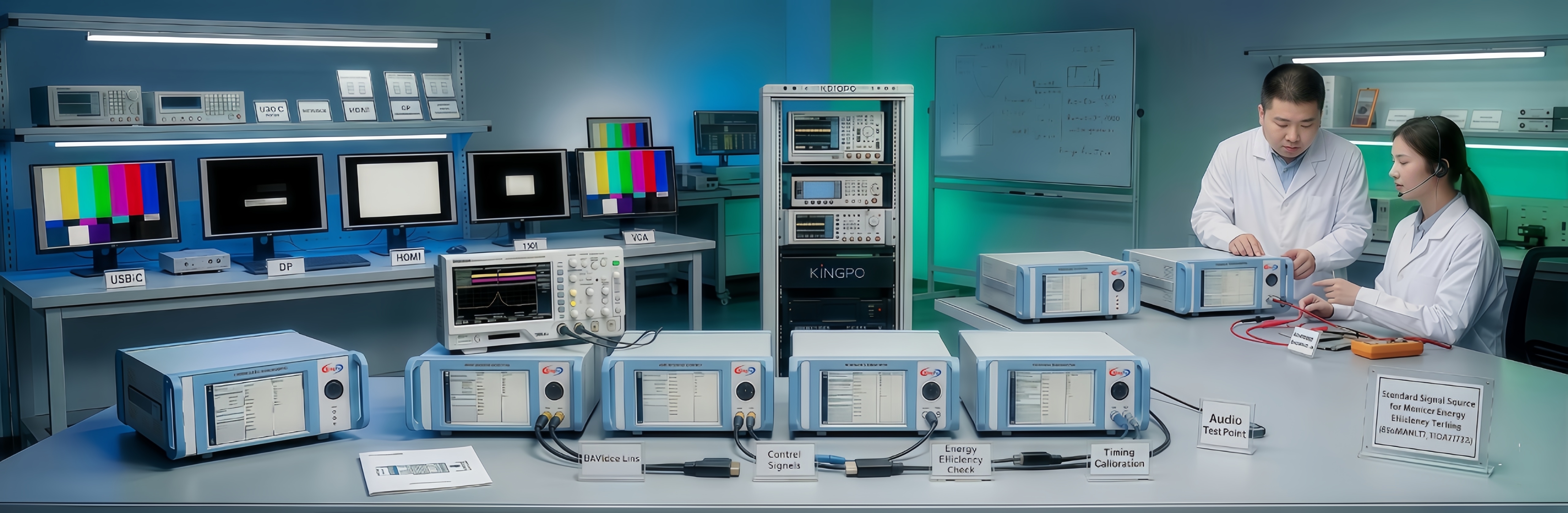
UL859 Hair dryer temperature test system | UL859-figure 44.4 spacings on thermocouple grid
The thermocouple grid assembly is to consist of two pieces of 1/16-inch (1.6-mm) thick glass epoxy board of the configuration and dimensions shown in Figure 44.4. The two boards are to be separated 1/8-inch (3.2-mm) by one 5-1/4- by 1/4- by 1/8-inch (133- by 6.4- by 3.2-mm) wood spacer at the top and bottom edges. Each spacer is to be secured by four 4 -40 by 3/8-inch countersunk flat head machine screws. Each end screw is to be threaded from the face of the assembly into a nut against the rear epoxy board. Each of the middle screws is to be located approximately 1-1/2 inches (38.1 mm) from the nearest longer edge of the board and threaded from the face into a standoff leg of a sheet aluminum back plate. The 5-1/2 by 3-1/4 inch (140 by 83 mm) stand-off back plate is to consist of sheet aluminum hat is 0.05 inch (1.3 mm) thick, having a minimum 7/16-inch (11.1-mm) wide integral standoff leg formed at each corner by means of an extension of the metal being bent in two successive 90-degree angles to cause the back plate to stand away from the rear epoxy board a distance of 1/4 inch. The back plate is to be secured to the center 5-1/2 by 3-1/4 inch section of the board. The board assembly is to be provided with 53 thermocouples rated 30 AWG (0.05 mm2). The thermocouples are to be located on the grid spaced as shown in Figure 44.4. The thermocouples are to be passed through the two thicknesses of glass epoxy board, and the thermocouple junction is to be cemented to the face of the board using epoxy cement, as shown in Figure 44.5.
![]()
![]()
![]()
![]()

|
|
| MOQ: | 1 |
| Price: | To be quoted |
| Standard Packaging: | safety carton pack or plywood box |
| Delivery Period: | 20 working days |
| Payment Method: | T/T |
| Supply Capacity: | 1000 pcs |
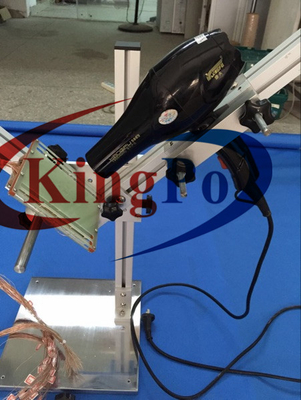
UL859 Hair dryer temperature test system | UL859-figure 44.4 spacings on thermocouple grid
The thermocouple grid assembly is to consist of two pieces of 1/16-inch (1.6-mm) thick glass epoxy board of the configuration and dimensions shown in Figure 44.4. The two boards are to be separated 1/8-inch (3.2-mm) by one 5-1/4- by 1/4- by 1/8-inch (133- by 6.4- by 3.2-mm) wood spacer at the top and bottom edges. Each spacer is to be secured by four 4 -40 by 3/8-inch countersunk flat head machine screws. Each end screw is to be threaded from the face of the assembly into a nut against the rear epoxy board. Each of the middle screws is to be located approximately 1-1/2 inches (38.1 mm) from the nearest longer edge of the board and threaded from the face into a standoff leg of a sheet aluminum back plate. The 5-1/2 by 3-1/4 inch (140 by 83 mm) stand-off back plate is to consist of sheet aluminum hat is 0.05 inch (1.3 mm) thick, having a minimum 7/16-inch (11.1-mm) wide integral standoff leg formed at each corner by means of an extension of the metal being bent in two successive 90-degree angles to cause the back plate to stand away from the rear epoxy board a distance of 1/4 inch. The back plate is to be secured to the center 5-1/2 by 3-1/4 inch section of the board. The board assembly is to be provided with 53 thermocouples rated 30 AWG (0.05 mm2). The thermocouples are to be located on the grid spaced as shown in Figure 44.4. The thermocouples are to be passed through the two thicknesses of glass epoxy board, and the thermocouple junction is to be cemented to the face of the board using epoxy cement, as shown in Figure 44.5.
![]()
![]()
![]()
![]()
address
RM C, 13/F, HARVARD COMMERCIAL BUILDING, 105-111 THOMSON ROAD, WAN CHAI, HK
tel
86-769- 81627526