
|
| MOQ: | 1 |
| Price: | To be quoted |
| Standard Packaging: | safety carton pack or plywood box |
| Delivery Period: | goods in stock |
| Payment Method: | T/T |
| Supply Capacity: | 10 set/ month |
USB Type-C Connectors and Cable Assemblies Compliance - Figure E-3 Reference Wrenching Strength Continuity Test Fixture
E Wrenching Strength Test
Type-C plugs on cable assemblies and fixtured plug component parts without overmold shall be tested using the mechanical wrenching test fixture, as illustrated in Figure E-1. The fixture substitutes machined metal parts for the receptacle. For plug component part testing, the supplier shall provide a plug test fixture that conforms to the specified plug overmold dimensions for the Type-C plug. See Figure E-2. The fixture may be metal or other suitable material. Perpendicular moments are applied to the plug with a 5 mm ball tipped probe for a period of at least 10 seconds when inserted in the test fixture to achieve the defined moments in four directions of up or down (i.e., perpendicular to the long axis of the plug opening) and left or right (i.e., in the plane of the plug opening). Compliant connectors shall meet the following force thresholds:
a) A moment of 0-0.75 Nm (e.g., 50 N at 15 mm from the edge of the receptacle) is applied to a plug inserted in the test fixture in each of the four directions. A single plug shall be used for this test. Some mechanical deformation may occur. The plug shall be mated with the continuity test fixture after the test forces have been applied to verify no damage has occurred that causes discontinuity or shorting. The continuity test fixture shall provide a planar surface on the mating side located 6.20 ± 0.20 mm from the receptacle Datum A, perpendicular to the direction of insertion. No moment forces are applied to the plug during this continuity test. Figure E-3 illustrates an example continuity test fixture to perform the continuity test. The Dielectric Withstanding Voltage test shall be conducted after the continuity test to verify plug compliance.
b) The plug shall disengage from the test fixture or demonstrate mechanical failure (i.e., the force applied during the test procedure peaks and drops off) when a moment of 2.0 Nm is applied to the plug in the up and down directions and a moment 3.5 Nm is applied to the plug in the left and right directions. A new plug is required for each of the four test directions. An example of the mechanical failure point is shown in Figure
![]()

|
|
| MOQ: | 1 |
| Price: | To be quoted |
| Standard Packaging: | safety carton pack or plywood box |
| Delivery Period: | goods in stock |
| Payment Method: | T/T |
| Supply Capacity: | 10 set/ month |
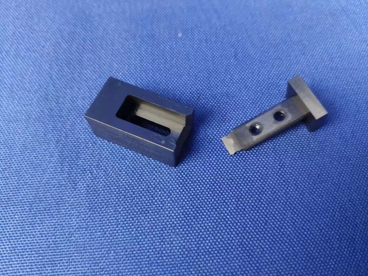
USB Type-C Connectors and Cable Assemblies Compliance - Figure E-3 Reference Wrenching Strength Continuity Test Fixture
E Wrenching Strength Test
Type-C plugs on cable assemblies and fixtured plug component parts without overmold shall be tested using the mechanical wrenching test fixture, as illustrated in Figure E-1. The fixture substitutes machined metal parts for the receptacle. For plug component part testing, the supplier shall provide a plug test fixture that conforms to the specified plug overmold dimensions for the Type-C plug. See Figure E-2. The fixture may be metal or other suitable material. Perpendicular moments are applied to the plug with a 5 mm ball tipped probe for a period of at least 10 seconds when inserted in the test fixture to achieve the defined moments in four directions of up or down (i.e., perpendicular to the long axis of the plug opening) and left or right (i.e., in the plane of the plug opening). Compliant connectors shall meet the following force thresholds:
a) A moment of 0-0.75 Nm (e.g., 50 N at 15 mm from the edge of the receptacle) is applied to a plug inserted in the test fixture in each of the four directions. A single plug shall be used for this test. Some mechanical deformation may occur. The plug shall be mated with the continuity test fixture after the test forces have been applied to verify no damage has occurred that causes discontinuity or shorting. The continuity test fixture shall provide a planar surface on the mating side located 6.20 ± 0.20 mm from the receptacle Datum A, perpendicular to the direction of insertion. No moment forces are applied to the plug during this continuity test. Figure E-3 illustrates an example continuity test fixture to perform the continuity test. The Dielectric Withstanding Voltage test shall be conducted after the continuity test to verify plug compliance.
b) The plug shall disengage from the test fixture or demonstrate mechanical failure (i.e., the force applied during the test procedure peaks and drops off) when a moment of 2.0 Nm is applied to the plug in the up and down directions and a moment 3.5 Nm is applied to the plug in the left and right directions. A new plug is required for each of the four test directions. An example of the mechanical failure point is shown in Figure
![]()
address
RM C, 13/F, HARVARD COMMERCIAL BUILDING, 105-111 THOMSON ROAD, WAN CHAI, HK
tel
86-769- 81627526