|
| MOQ: | 1 |
| Price: | 9999 |
| Standard Packaging: | 1000*1000*1000CM |
| Payment Method: | T/T |
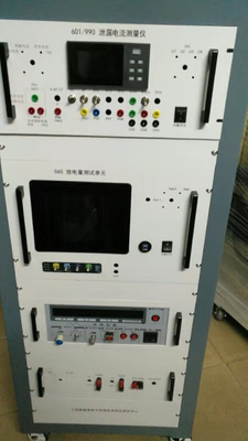
601 / 990 Contact current-terminal discharge tester Technical specification
Type 601 Contact current-terminal discharge tester...
1, overview
This instrument is a
, information technology equipment and electronic and electrical contact current, leakage current and terminal discharge instrument.Contact current (leakage current) and terminal discharge volume are general measuring instruments in the laboratory engaged in electronic and electrical product safety testing, widely suitable for electronic and electrical product safety standards compliance tests, e. g. (not limited to this):IEC60065/GB8898;IEC60950/GB4943;IEC60335/GB7000;IEC62109-1;IEC60598/GB7000.1;IEC61010/GB4793;IEC60601; IEC60060 and other electronic and electrical safety standards.
On the basis of the general measurement function of contact current and terminal discharge of electronic and electrical products, the current situation of measurement and analysis design of medical electronic equipment system in China and the world, and the measurement unit of contact current of medical electronic equipment system / leakage current.The measurement principle and basic circuit of the unit are fully designed in accordance with the international standards IEC60601-1 Basic Requirements for the Safety of Medical Electronic Equipment and IEC60990 Human Contact Current and Protection Conductor Current Measurement Method, considering the use experience and requirements of the authoritative safety regulation laboratory, simple operation, safe and reliable;
Therefore, two sets of test systems (systems 1 and system 2) are designed to realize the terminal discharge quantity measurement and contact current measurement.System 1 is the test principle of the data acquisition card. The test system has high measurement accuracy and automatically locks in the negative peak of the sinine wave for measurement, which meets the requirements of the IECEE-CTL resolution.The contact current measurement adopts the "root mean square principle" to obtain the true effective value. The method can accurately measure the irregular contact current. Due to the input of data acquisition card difference, the acquisition card reads the contact current envelope waveform, which effectively solves the effect of superimposed interference pulse on the peak of contact current measurement by oscilloscope.
The system 2 adopts a built-in 100MHzUSB oscilloscope, whose use functions, technical parameters and calibration are the same as the traditional oscilloscope.Compared to the data acquisition card measurement principle of system 1, the advantage of the oscilloscope is to measure the high frequency, the contact current at high frequency, and is calibrated by a general method, however, the operation and setting are relatively complex, and the accuracy is slightly lower, and the waveform is susceptible to interference.
The functions and technical parameters of this instrument are as follows:
I, Contact current test function
Test circuit layout with single-phase power supply of TN or TT power supply network specified in IEC60990, including protection conductor on, off state (PE ON / OFF), midline conductor on, off state (N ON / OFF); and power supply phase line, midline polarity conversion state; (L-N Polarity reverse);
Second, the terminal discharge quantity test function
measuring accuracy:
0-9999V dc,0.3%F.S.±2 digit
Display time error is 0.5%.
Resistance error: 0.5%,
Capacacitive error: 1.0%,
testing software
safety precautions:
![]()
This instrument is equipped with two test systems, Sys.1, and Sys.2.
Sys.1 The measurement principle of the data collector is to accurately control the measurement phase of the terminal discharge volume to achieve rapid and accurate measurements as per the IECEE-CTL resolution.In terms of measuring the leakage current, the leakage current and the leakage voltage U can be accurately given1,U2,U3The peak and true effective values of the.
Sys.2 The traditional oscilloscope measurement method is used, the DSO2250 type USB100M oscilloscope is embedded inside the instrument, and the method and calibration method are completely identical to the universal oscilloscope.
Before testing, the measurement software system is first installed for the computer, including the data acquisition system Sys.1 Measurement software and USB oscilloscope test system Sys.2 Measurement software DSO2250; then determine that the leakage protection switch of the backplane is placed in the open position, and the internal and external power conversion switch is located in the internal power supply is (In).
System 1 measurement operation
1 Terminal discharge volume measurement
1.1 Panel function settings:
1.2 Connect to the measuring computer
A) Connect the system 1 (the USB port on the left side of the panel) to the computer with a randomly provided USB measurement line. After the computer is turned on, the green light on the side of the USB port flashes, indicating that the data communication is normal.
1.3 Instrument power supply connection and sample connection
The inverter AC voltage module of the panel will display an AC voltage, the sample test voltage, with the adjusted voltage adjustment knob, which can vary between 0 and 250V.Adjust the voltage to the desired test voltage, e. g., 220V.Also do not forget to adjust the power frequency to the required test frequency, for example: 60Hz.
1.4 Measurement operation
![]()
If there is a series of sine wave, usually because the trigger level is not high enough, adjust the right knob and adjust the trigger level displayed by the right instrument to about 110V, both the default value.
The initial value of the operating system software shall be set as follows:
2. Contact current and leakage current measurement
2.1 Panel function settings:
2.2 Connect to the built-in industrial control machine
A) Connect system 1 (USB port on the left side of the panel) to the built-in controller with a randomly provided USB measurement line. After opening the controller, the green light on the side of the USB port flashes, indicating that the data communication is normal.
2.4 Measurement operation
A) After confirming that the instrument is correctly connected to the external monitor (desktop computer or laptop) (panel green indicator light flashing), open the data collection card operating system and enter the contact current test bar;
The b) Conduct self-verification (if necessary).Use voltage is 12Vr.m.The external AC power supply of s is input to the leakage current test input port and, normally, the instrument shall display 3Vr.m.s voltage effective value and the corresponding peak of 4.22Vp (1 / 4 of the input voltage), show the self-calibration current of 6mAr.m.And 8.4mAp (sampling resistance at 500 Ω), as shown in Fig.
c) Use the measuring line with the crocodile clip, connect the red terminal of the measuring port to the measured part of the measured sample, and then click the "leakage current measurement" button in the system parameter bar. If normal, the computer shall display the following figure.
The d) respective measurement limit ports of the panel are configured in accordance with FIGS. 4-19 of IEC60601-1 and IEC60990, and identify the respective measurement ports of the panel according to the standard test diagram.The user directly connects the test samples according to the standard test circuit, and makes the above measurements under different fault settings and different network settings to obtain the corresponding contact current peak and effective value.
The initial value of the operating system software shall be set as follows:
This test software reads the peak voltage on the 500 Ω resistance and the true effective value voltage read by the root mean square principle, and then divided by 500 to obtain the peak contact current and the true effective value current.
The default conversion coefficient of the voltage of this test software is 1, and the user can modify it itself, however, if there is no determined data support, it is not recommended to modify the voltage conversion coefficient by itself.
Setting up the operating system can change the waveform color and shape.
Through the operating system, the waveform can be saved.
![]()
![]()
Self-check waveform
![]()
Measured leakage current waveform
Measurement operation of system 2
1 Terminal discharge volume measurement
1.1 Panel function settings:
1.2 Power supply connection and sample connection
1.4 USB oscilloscope settings
Since the sample supply voltage sine wave is not necessarily at the peak when dialing the "polar switch" for the measurement, repeated measurements are required to obtain the ideal discharge waveform for the peak discharge.
![]()
The power recorder of the current leakage current measurement unit of medical device is a comprehensive study of electronic Weihai information technology
The center is suitable for the rapid development of China's medical and electronic industry and the relevant international standards
A measurement and analysis system developed for the serious shortage of safety detection capability.
The system is IEC 60601 for the medical equipment,
Special measurement equipment developed for international standards like GB9706 and national mandatory standards, can complete tests of all patient contact current, patient auxiliary current and patient contact current specified by international standard IEC60601.
the key technical indexes
Figure 15 The same type of patient was applied to the same type of patient currents connected together
Figure 16 Patient current after patient application of external voltage
Inputs and outputs of FIG. 17 ME are applied with a patient current after an external voltage
FIG. 18 ME The unprotected grounded housing is applied to the patient current after an external voltage
Figure 19 ME total patient current after ligation by all patients
R to input / output terminal, contact current measurement, Figure 14,
R to input / output terminal, patient current measurement, Figure 17
R to metal shell, patient current measurement, Figure 18
R to patient current MD, the other end of MD to class F patient applied terminals, Figure 16
Standard reference figure:
![]()
![]()
![]()
![]()
![]()
![]()
IV. Waveform output monitoring:
International standards and national standards require the measurement of the true effective value of patient current, and the waveform coefficients of patient current / patient contact current are different, which cannot use the known fixed relationship between "effective value and peak". Therefore, this instrument is equipped with two ways to monitor the effective value and peak of leakage current in real time:
l Peak leakage current and discharge volume waveform were monitored with a data acquisition card and a USB oscilloscope;
l The true effective value is measured with the digital ammeter / voltmeter of the integral principle, which can be compared with the peak of the data acquisition card for the conversion, if necessary.
The above features can operate on the selector switch on the panel:
Pulse output waveforms were monitored in real-time using data acquisition cards
The data acquisition card time coordinate is set to four gears:
CH1 IEC60990 contact current, used for monitoring the contact current pulse waveform monitoring;
The CH2 IEC60601 contact current, the patient current, was used to monitor the patient current peak waveform monitoring;
CH3 IEC60601 patient auxiliary current, used to monitor patient auxiliary current peak waveform monitoring;
CH4 IEC60065 terminal discharge, used to monitor terminal discharge peak waveform monitoring;
The data collector (the USB oscilloscope can be used) to monitor the frequency conversion voltage and the current output waveform. When the nonlinear steep increase in the waveform occurs, the insulation breakdown or deterioration of the tested sample occurs.
Charge and discharge time was used to select and control the data collector software, number of pulses, and time coordinates.
Peak current waveforms were monitored in real-time using an oscilloscope
The USB oscilloscope is built-in. The user can choose the oscilloscope to monitor and calibrate the output waveform. When the acquisition rate of the data collector is not high enough, the monitoring waveform curve point is not dense enough.
Built-in adjustment is used to monitor the pulse waveform with a USB oscilloscope and touch
Hair adjustment is identical to the ordinary oscilloscope.The pulse output interval and pulse output number are still controlled by the data collector software interface.
This instrument uses the industrial controller waveform display, can be controlled through the panel port external mouse, or screen touch.
V. Measurement error (precision)
Paper less recorder: monitoring voltage, current: 0.5%F.S.±2 digit
USB oscilloscope: 4-channel 60MHz
Base accuracy of horizontal system: ± 50 ppm
Vertical resolution: 8 Bit
Vertical gain accuracy: ± 3%
Self-calibrated signal output: 1Hz square wave / 2Vp-p
USB collector:
Acquisition rate: 500KS / s
± 10V full-range absolute accuracy:
14.7mV(25℃);
138mV (unconventional temperature maximum)
Six, protection measures
The instrument is a Class I safety protection design, and all operator-contact metal parts of the enclosure are subjected to the electric resistance strength voltage of 1500VAC;
The measuring circuit of this instrument is floating ground design and can be directly connected to oscilloscope, etc;
This instrument is equipped with a leakage protection switch, which provides cut-off protection for the measurement of the circuit overload short circuit or the ground leakage current exceeds the limited value, requiring manual reset;
A 3A fuse is built in the power input socket of this instrument for circuit protection when an overload short circuit occurs in the non-measuring load circuit inside the instrument.
The frequency conversion power supply output is equipped with an overcurrent alarm, which will be automatically cut off when the current is too large.
Seven, the use of the environment
temperature:0-50℃
Humidity: 80%R.H.(No condensation)
Air pressure: 96-106kPa
Power supply: 220V ± 10%, single-phase + protection ground
Each channel has the corresponding output port, please select correctly.
Seven, operating system
The randomly provided application requires the following operating system: Windows 7 (recommended)
Eight, operating system
The randomly provided application requires the following operating system: Windows 7 (recommended)

|
|
| MOQ: | 1 |
| Price: | 9999 |
| Standard Packaging: | 1000*1000*1000CM |
| Payment Method: | T/T |
601 / 990 Contact current-terminal discharge tester Technical specification
Type 601 Contact current-terminal discharge tester...
1, overview
This instrument is a
, information technology equipment and electronic and electrical contact current, leakage current and terminal discharge instrument.Contact current (leakage current) and terminal discharge volume are general measuring instruments in the laboratory engaged in electronic and electrical product safety testing, widely suitable for electronic and electrical product safety standards compliance tests, e. g. (not limited to this):IEC60065/GB8898;IEC60950/GB4943;IEC60335/GB7000;IEC62109-1;IEC60598/GB7000.1;IEC61010/GB4793;IEC60601; IEC60060 and other electronic and electrical safety standards.
On the basis of the general measurement function of contact current and terminal discharge of electronic and electrical products, the current situation of measurement and analysis design of medical electronic equipment system in China and the world, and the measurement unit of contact current of medical electronic equipment system / leakage current.The measurement principle and basic circuit of the unit are fully designed in accordance with the international standards IEC60601-1 Basic Requirements for the Safety of Medical Electronic Equipment and IEC60990 Human Contact Current and Protection Conductor Current Measurement Method, considering the use experience and requirements of the authoritative safety regulation laboratory, simple operation, safe and reliable;
Therefore, two sets of test systems (systems 1 and system 2) are designed to realize the terminal discharge quantity measurement and contact current measurement.System 1 is the test principle of the data acquisition card. The test system has high measurement accuracy and automatically locks in the negative peak of the sinine wave for measurement, which meets the requirements of the IECEE-CTL resolution.The contact current measurement adopts the "root mean square principle" to obtain the true effective value. The method can accurately measure the irregular contact current. Due to the input of data acquisition card difference, the acquisition card reads the contact current envelope waveform, which effectively solves the effect of superimposed interference pulse on the peak of contact current measurement by oscilloscope.
The system 2 adopts a built-in 100MHzUSB oscilloscope, whose use functions, technical parameters and calibration are the same as the traditional oscilloscope.Compared to the data acquisition card measurement principle of system 1, the advantage of the oscilloscope is to measure the high frequency, the contact current at high frequency, and is calibrated by a general method, however, the operation and setting are relatively complex, and the accuracy is slightly lower, and the waveform is susceptible to interference.
The functions and technical parameters of this instrument are as follows:
I, Contact current test function
Test circuit layout with single-phase power supply of TN or TT power supply network specified in IEC60990, including protection conductor on, off state (PE ON / OFF), midline conductor on, off state (N ON / OFF); and power supply phase line, midline polarity conversion state; (L-N Polarity reverse);
Second, the terminal discharge quantity test function
measuring accuracy:
0-9999V dc,0.3%F.S.±2 digit
Display time error is 0.5%.
Resistance error: 0.5%,
Capacacitive error: 1.0%,
testing software
safety precautions:
![]()
This instrument is equipped with two test systems, Sys.1, and Sys.2.
Sys.1 The measurement principle of the data collector is to accurately control the measurement phase of the terminal discharge volume to achieve rapid and accurate measurements as per the IECEE-CTL resolution.In terms of measuring the leakage current, the leakage current and the leakage voltage U can be accurately given1,U2,U3The peak and true effective values of the.
Sys.2 The traditional oscilloscope measurement method is used, the DSO2250 type USB100M oscilloscope is embedded inside the instrument, and the method and calibration method are completely identical to the universal oscilloscope.
Before testing, the measurement software system is first installed for the computer, including the data acquisition system Sys.1 Measurement software and USB oscilloscope test system Sys.2 Measurement software DSO2250; then determine that the leakage protection switch of the backplane is placed in the open position, and the internal and external power conversion switch is located in the internal power supply is (In).
System 1 measurement operation
1 Terminal discharge volume measurement
1.1 Panel function settings:
1.2 Connect to the measuring computer
A) Connect the system 1 (the USB port on the left side of the panel) to the computer with a randomly provided USB measurement line. After the computer is turned on, the green light on the side of the USB port flashes, indicating that the data communication is normal.
1.3 Instrument power supply connection and sample connection
The inverter AC voltage module of the panel will display an AC voltage, the sample test voltage, with the adjusted voltage adjustment knob, which can vary between 0 and 250V.Adjust the voltage to the desired test voltage, e. g., 220V.Also do not forget to adjust the power frequency to the required test frequency, for example: 60Hz.
1.4 Measurement operation
![]()
If there is a series of sine wave, usually because the trigger level is not high enough, adjust the right knob and adjust the trigger level displayed by the right instrument to about 110V, both the default value.
The initial value of the operating system software shall be set as follows:
2. Contact current and leakage current measurement
2.1 Panel function settings:
2.2 Connect to the built-in industrial control machine
A) Connect system 1 (USB port on the left side of the panel) to the built-in controller with a randomly provided USB measurement line. After opening the controller, the green light on the side of the USB port flashes, indicating that the data communication is normal.
2.4 Measurement operation
A) After confirming that the instrument is correctly connected to the external monitor (desktop computer or laptop) (panel green indicator light flashing), open the data collection card operating system and enter the contact current test bar;
The b) Conduct self-verification (if necessary).Use voltage is 12Vr.m.The external AC power supply of s is input to the leakage current test input port and, normally, the instrument shall display 3Vr.m.s voltage effective value and the corresponding peak of 4.22Vp (1 / 4 of the input voltage), show the self-calibration current of 6mAr.m.And 8.4mAp (sampling resistance at 500 Ω), as shown in Fig.
c) Use the measuring line with the crocodile clip, connect the red terminal of the measuring port to the measured part of the measured sample, and then click the "leakage current measurement" button in the system parameter bar. If normal, the computer shall display the following figure.
The d) respective measurement limit ports of the panel are configured in accordance with FIGS. 4-19 of IEC60601-1 and IEC60990, and identify the respective measurement ports of the panel according to the standard test diagram.The user directly connects the test samples according to the standard test circuit, and makes the above measurements under different fault settings and different network settings to obtain the corresponding contact current peak and effective value.
The initial value of the operating system software shall be set as follows:
This test software reads the peak voltage on the 500 Ω resistance and the true effective value voltage read by the root mean square principle, and then divided by 500 to obtain the peak contact current and the true effective value current.
The default conversion coefficient of the voltage of this test software is 1, and the user can modify it itself, however, if there is no determined data support, it is not recommended to modify the voltage conversion coefficient by itself.
Setting up the operating system can change the waveform color and shape.
Through the operating system, the waveform can be saved.
![]()
![]()
Self-check waveform
![]()
Measured leakage current waveform
Measurement operation of system 2
1 Terminal discharge volume measurement
1.1 Panel function settings:
1.2 Power supply connection and sample connection
1.4 USB oscilloscope settings
Since the sample supply voltage sine wave is not necessarily at the peak when dialing the "polar switch" for the measurement, repeated measurements are required to obtain the ideal discharge waveform for the peak discharge.
![]()
The power recorder of the current leakage current measurement unit of medical device is a comprehensive study of electronic Weihai information technology
The center is suitable for the rapid development of China's medical and electronic industry and the relevant international standards
A measurement and analysis system developed for the serious shortage of safety detection capability.
The system is IEC 60601 for the medical equipment,
Special measurement equipment developed for international standards like GB9706 and national mandatory standards, can complete tests of all patient contact current, patient auxiliary current and patient contact current specified by international standard IEC60601.
the key technical indexes
Figure 15 The same type of patient was applied to the same type of patient currents connected together
Figure 16 Patient current after patient application of external voltage
Inputs and outputs of FIG. 17 ME are applied with a patient current after an external voltage
FIG. 18 ME The unprotected grounded housing is applied to the patient current after an external voltage
Figure 19 ME total patient current after ligation by all patients
R to input / output terminal, contact current measurement, Figure 14,
R to input / output terminal, patient current measurement, Figure 17
R to metal shell, patient current measurement, Figure 18
R to patient current MD, the other end of MD to class F patient applied terminals, Figure 16
Standard reference figure:
![]()
![]()
![]()
![]()
![]()
![]()
IV. Waveform output monitoring:
International standards and national standards require the measurement of the true effective value of patient current, and the waveform coefficients of patient current / patient contact current are different, which cannot use the known fixed relationship between "effective value and peak". Therefore, this instrument is equipped with two ways to monitor the effective value and peak of leakage current in real time:
l Peak leakage current and discharge volume waveform were monitored with a data acquisition card and a USB oscilloscope;
l The true effective value is measured with the digital ammeter / voltmeter of the integral principle, which can be compared with the peak of the data acquisition card for the conversion, if necessary.
The above features can operate on the selector switch on the panel:
Pulse output waveforms were monitored in real-time using data acquisition cards
The data acquisition card time coordinate is set to four gears:
CH1 IEC60990 contact current, used for monitoring the contact current pulse waveform monitoring;
The CH2 IEC60601 contact current, the patient current, was used to monitor the patient current peak waveform monitoring;
CH3 IEC60601 patient auxiliary current, used to monitor patient auxiliary current peak waveform monitoring;
CH4 IEC60065 terminal discharge, used to monitor terminal discharge peak waveform monitoring;
The data collector (the USB oscilloscope can be used) to monitor the frequency conversion voltage and the current output waveform. When the nonlinear steep increase in the waveform occurs, the insulation breakdown or deterioration of the tested sample occurs.
Charge and discharge time was used to select and control the data collector software, number of pulses, and time coordinates.
Peak current waveforms were monitored in real-time using an oscilloscope
The USB oscilloscope is built-in. The user can choose the oscilloscope to monitor and calibrate the output waveform. When the acquisition rate of the data collector is not high enough, the monitoring waveform curve point is not dense enough.
Built-in adjustment is used to monitor the pulse waveform with a USB oscilloscope and touch
Hair adjustment is identical to the ordinary oscilloscope.The pulse output interval and pulse output number are still controlled by the data collector software interface.
This instrument uses the industrial controller waveform display, can be controlled through the panel port external mouse, or screen touch.
V. Measurement error (precision)
Paper less recorder: monitoring voltage, current: 0.5%F.S.±2 digit
USB oscilloscope: 4-channel 60MHz
Base accuracy of horizontal system: ± 50 ppm
Vertical resolution: 8 Bit
Vertical gain accuracy: ± 3%
Self-calibrated signal output: 1Hz square wave / 2Vp-p
USB collector:
Acquisition rate: 500KS / s
± 10V full-range absolute accuracy:
14.7mV(25℃);
138mV (unconventional temperature maximum)
Six, protection measures
The instrument is a Class I safety protection design, and all operator-contact metal parts of the enclosure are subjected to the electric resistance strength voltage of 1500VAC;
The measuring circuit of this instrument is floating ground design and can be directly connected to oscilloscope, etc;
This instrument is equipped with a leakage protection switch, which provides cut-off protection for the measurement of the circuit overload short circuit or the ground leakage current exceeds the limited value, requiring manual reset;
A 3A fuse is built in the power input socket of this instrument for circuit protection when an overload short circuit occurs in the non-measuring load circuit inside the instrument.
The frequency conversion power supply output is equipped with an overcurrent alarm, which will be automatically cut off when the current is too large.
Seven, the use of the environment
temperature:0-50℃
Humidity: 80%R.H.(No condensation)
Air pressure: 96-106kPa
Power supply: 220V ± 10%, single-phase + protection ground
Each channel has the corresponding output port, please select correctly.
Seven, operating system
The randomly provided application requires the following operating system: Windows 7 (recommended)
Eight, operating system
The randomly provided application requires the following operating system: Windows 7 (recommended)
address
RM C, 13/F, HARVARD COMMERCIAL BUILDING, 105-111 THOMSON ROAD, WAN CHAI, HK
tel
86-769- 81627526