

|
| MOQ: | 1 |
| Price: | To be quoted |
| Standard Packaging: | safety carton pack or plywood box |
| Delivery Period: | goods in stock |
| Payment Method: | T/T |
| Supply Capacity: | 1000 pcs |
5.2.2.1 Test tabs for the insertion-withdrawal test described in Clause 6.4 shall be made of unplated brass, identified as CDA C26000 Alloy with a hardness of 62 ±7 on the Rockwell 30T scale.
5.2.2.2 Test tabs for the temperature and current cycling tests described in Clause 6.5 shall be made of tin-plated steel or corrosion resistant steel having a hardness of 68 ±5 on the Rockwell 30T scale.
5.2.2.3 In regard to Clause 5.2.2.2, for connectors intended exclusively for use with production tabs of copper alloy, an unplated brass test tab of C26000 Alloy with a hardness of 62 ±7 on the Rockwell 30T scale may be used.
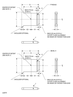
5.3.3.1 Single-ended test tabs for the insertion-withdrawal test shall have the configuration shown in Figures 2 to 4 and the dimensions specified in Tables 2 and 3. The "C" dimension tolerance shall be ±0.008 mm (0.0003 in) for brass and ±0.013 mm (0.0005 in) for steel, and raised plateaus around the detent shall be limited to a combined total of 0.03 mm (0.001 in) for both sides.
5.3.3.2 Double-ended test tabs for the temperature and current cycling tests shall be constructed in accordance with Clause 5.3.3.1 and have the configuration shown in Figure 5.
(See note to Figure 5)
| Nominal size | A | B(min) | C | D | E | F | J | M | N | P | Q(min) |
| 2.8 x 0.5 with dimple | 0.6 | 7.0 | 0.54 | 2.90 | 1.8 | 1.3 | 12° | 1.7 | 1.4 | 1.4 | 8.1 |
| 0.3 | 0.47 | 2.70 | 1.3 | 1.1 | 8° | 1.4 | 1.0 | 0.3 | |||
| 2.8 x 0.5 with hole | 0.6 | 7.0 | 0.54 | 2.90 | 1.8 | 1.3 | 12° | 1.4 | 8.1 | ||
| 0.3 | 0.47 | 2.70 | 1.3 | 1.1 | 8° | 0.3 | |||||
| 2.8 x 0.8 with dimple | 0.6 | 7.0 | 0.84 | 2.90 | 1.8 | 1.3 | 12° | 1.7 | 1.4 | 1.4 | 8.1 |
| 0.3 | 0.77 | 2.70 | 1.3 | 1.1 | 8° | 1.4 | 1.0 | 0.3 | |||
| 2.8 x 0.8 with hole | 0.6 | 7.0 | 0.84 | 2.90 | 1.8 | 1.3 | 12° | 1.4 | 8.1 | ||
| 0.3 | 0.77 | 2.70 | 1.3 | 1.1 | 8° | 0.3 | |||||
| 3.2 x 0.8 with dimple | 0.6 | 7.0 | 0.84 | 3.25 | 1.8 | 1.3 | 12° | 1.7 | 1.4 | 1.4 | 8.1 |
| 0.3 | 0.79 | 3.10 | 1.4 | 1.1 | 8° | 1.4 | 1.1 | 0.3 | |||
| 3.2 x 0.8 with hole | 0.6 | 7.0 | 0.84 | 3.25 | 1.8 | 1.3 | 12° | 1.4 | 8.1 | ||
| 0.3 | 0.79 | 3.10 | 1.4 | 1.1 | 8° | 0.3 | |||||
| 3.2 x 0.5 with dimple | 0.6 | 7.0 | 0.54 | 3.25 | 1.8 | 1.3 | 12° | 1.7 | 1.4 | 1.4 | 8.1 |
| 0.3 | 0.48 | 3.10 | 1.4 | 1.1 | 8° | 1.4 | 1.1 | 0.3 | |||
| 3.2 x 0.5 with hole | 0.6 | 7.0 | 0.54 | 3.25 | 1.8 | 1.3 | 12° | 1.4 | 8.1 | ||
| 0.3 | 0.48 | 3.10 | 1.4 | 1.1 | 8° | 0.3 | |||||
| 4.8 x 0.5 with dimple | 0.9 | 6.2 | 0.54 | 4.80 | 2.8 | 1.5 | 12° | 1.7 | 1.5 | 1.7 | 7.3 |
| 0.6 | 0.47 | 4.60 | 2.3 | 1.3 | 8° | 1.4 | 1.2 | 0.6 | |||
| 4.8 x 0.5 with hole | 0.9 | 6.2 | 0.54 | 4.90 | 3.4 | 1.5 | 12° | 1.7 | 7.3 | ||
| 0.6 | 0.47 | 4.67 | 3.0 | 1.3 | 8° | 0.6 | |||||
| 4.8 x 0.8 with dimple | 1.0 | 6.2 | 0.84 | 4.80 | 2.8 | 1.5 | 12° | 1.7 | 1.5 | 1.8 | 7.3 |
| 0.7 | 0.77 | 4.60 | 2.3 | 1.3 | 8° | 1.4 | 1.2 | 0.7 | |||
| 4.8 x 0.8 with hole | 1.0 | 6.2 | 0.84 | 4.90 | 3.4 | 1.5 | 12° | 1.8 | 7.3 | ||
| 0.6 | 0.77 | 4.67 | 3.0 | 1.3 | 8° | 0.7 | |||||
| 5.2 x 0.5 with dimple | 1.0 | 6.2 | 0.54 | 5.30 | 2.8 | 1.9 | 12° | 2.5 | 2.0 | 1.7 | 7.3 |
| 0.7 | 0.47 | 5.10 | 2.3 | 1.6 | 8° | 2.2 | 1.8 | 0.6 | |||
| 5.2 x 0.5 with hole | 1.0 | 6.2 | 0.54 | 5.30 | 3.4 | 1.9 | 12° | 1.7 | 7.3 | ||
| 0.7 | 0.47 | 5.10 | 3.0 | 1.6 | 8° | 0.6 | |||||
| 5.2 x 0.8 with dimple | 1.0 | 6.2 | 0.84 | 5.30 | 2.8 | 1.9 | 12° | 2.5 | 2.0 | 1.8 | 7.3 |
| 0.7 | 0.77 | 5.10 | 2.3 | 1.6 | 8° | 2.2 | 1.8 | 0.7 | |||
| 5.2 x 0.8 with hole | 1.0 | 6.2 | 0.84 | 5.30 | 3.4 | 1.9 | 12° | 1.8 | 7.3 | ||
| 0.7 | 0.77 | 5.10 | 3.0 | 1.6 | 8° | 0.7 | |||||
| 6.3 x 0.8 with dimple | 1.0 | 7.8 | 0.84 | 6.40 | 4.1 | 2.0 | 12° | 2.5 | 2.0 | 1.8 | 8.9 |
| 0.7 | 0.77 | 6.20 | 3.6 | 1.6 | 8° | 2.2 | 1.8 | 0.7 | |||
| 6.3 x 0.8 with hole | 1.0 | 7.8 | 0.84 | 6.40 | 4.7 | 2.0 | 12° | 1.8 | 8.9 | ||
| 0.5 | 0.77 | 6.20 | 4.3 | 1.6 | 8° | 0.7 | |||||
| Notes: 1. Included are dimensions for those nominal sizes corresponding with those found in IEC 61210. 2. In the table where two values are provided, the lesser value is the minimum permitted value and the larger is the maximum permitted value. | |||||||||||
![]()
Note 1 - For dimple and hole detent dimensions F, G, M, and N, see Figures 3 and 4.
Note 2 - Bevel "H" need not be a straight line if it is within the confines shown, and it may be a radius of "P".
Note 3 - "Q" dimension is for tabs without shoulders.
Note 4 - "L" dimension not specified.
![]()
![]()
![]()
Note: See Figures 2 to 4 and Table 2 or 3.
![]()

|
|
| MOQ: | 1 |
| Price: | To be quoted |
| Standard Packaging: | safety carton pack or plywood box |
| Delivery Period: | goods in stock |
| Payment Method: | T/T |
| Supply Capacity: | 1000 pcs |
5.2.2.1 Test tabs for the insertion-withdrawal test described in Clause 6.4 shall be made of unplated brass, identified as CDA C26000 Alloy with a hardness of 62 ±7 on the Rockwell 30T scale.
5.2.2.2 Test tabs for the temperature and current cycling tests described in Clause 6.5 shall be made of tin-plated steel or corrosion resistant steel having a hardness of 68 ±5 on the Rockwell 30T scale.
5.2.2.3 In regard to Clause 5.2.2.2, for connectors intended exclusively for use with production tabs of copper alloy, an unplated brass test tab of C26000 Alloy with a hardness of 62 ±7 on the Rockwell 30T scale may be used.
5.3.3.1 Single-ended test tabs for the insertion-withdrawal test shall have the configuration shown in Figures 2 to 4 and the dimensions specified in Tables 2 and 3. The "C" dimension tolerance shall be ±0.008 mm (0.0003 in) for brass and ±0.013 mm (0.0005 in) for steel, and raised plateaus around the detent shall be limited to a combined total of 0.03 mm (0.001 in) for both sides.
5.3.3.2 Double-ended test tabs for the temperature and current cycling tests shall be constructed in accordance with Clause 5.3.3.1 and have the configuration shown in Figure 5.
(See note to Figure 5)
| Nominal size | A | B(min) | C | D | E | F | J | M | N | P | Q(min) |
| 2.8 x 0.5 with dimple | 0.6 | 7.0 | 0.54 | 2.90 | 1.8 | 1.3 | 12° | 1.7 | 1.4 | 1.4 | 8.1 |
| 0.3 | 0.47 | 2.70 | 1.3 | 1.1 | 8° | 1.4 | 1.0 | 0.3 | |||
| 2.8 x 0.5 with hole | 0.6 | 7.0 | 0.54 | 2.90 | 1.8 | 1.3 | 12° | 1.4 | 8.1 | ||
| 0.3 | 0.47 | 2.70 | 1.3 | 1.1 | 8° | 0.3 | |||||
| 2.8 x 0.8 with dimple | 0.6 | 7.0 | 0.84 | 2.90 | 1.8 | 1.3 | 12° | 1.7 | 1.4 | 1.4 | 8.1 |
| 0.3 | 0.77 | 2.70 | 1.3 | 1.1 | 8° | 1.4 | 1.0 | 0.3 | |||
| 2.8 x 0.8 with hole | 0.6 | 7.0 | 0.84 | 2.90 | 1.8 | 1.3 | 12° | 1.4 | 8.1 | ||
| 0.3 | 0.77 | 2.70 | 1.3 | 1.1 | 8° | 0.3 | |||||
| 3.2 x 0.8 with dimple | 0.6 | 7.0 | 0.84 | 3.25 | 1.8 | 1.3 | 12° | 1.7 | 1.4 | 1.4 | 8.1 |
| 0.3 | 0.79 | 3.10 | 1.4 | 1.1 | 8° | 1.4 | 1.1 | 0.3 | |||
| 3.2 x 0.8 with hole | 0.6 | 7.0 | 0.84 | 3.25 | 1.8 | 1.3 | 12° | 1.4 | 8.1 | ||
| 0.3 | 0.79 | 3.10 | 1.4 | 1.1 | 8° | 0.3 | |||||
| 3.2 x 0.5 with dimple | 0.6 | 7.0 | 0.54 | 3.25 | 1.8 | 1.3 | 12° | 1.7 | 1.4 | 1.4 | 8.1 |
| 0.3 | 0.48 | 3.10 | 1.4 | 1.1 | 8° | 1.4 | 1.1 | 0.3 | |||
| 3.2 x 0.5 with hole | 0.6 | 7.0 | 0.54 | 3.25 | 1.8 | 1.3 | 12° | 1.4 | 8.1 | ||
| 0.3 | 0.48 | 3.10 | 1.4 | 1.1 | 8° | 0.3 | |||||
| 4.8 x 0.5 with dimple | 0.9 | 6.2 | 0.54 | 4.80 | 2.8 | 1.5 | 12° | 1.7 | 1.5 | 1.7 | 7.3 |
| 0.6 | 0.47 | 4.60 | 2.3 | 1.3 | 8° | 1.4 | 1.2 | 0.6 | |||
| 4.8 x 0.5 with hole | 0.9 | 6.2 | 0.54 | 4.90 | 3.4 | 1.5 | 12° | 1.7 | 7.3 | ||
| 0.6 | 0.47 | 4.67 | 3.0 | 1.3 | 8° | 0.6 | |||||
| 4.8 x 0.8 with dimple | 1.0 | 6.2 | 0.84 | 4.80 | 2.8 | 1.5 | 12° | 1.7 | 1.5 | 1.8 | 7.3 |
| 0.7 | 0.77 | 4.60 | 2.3 | 1.3 | 8° | 1.4 | 1.2 | 0.7 | |||
| 4.8 x 0.8 with hole | 1.0 | 6.2 | 0.84 | 4.90 | 3.4 | 1.5 | 12° | 1.8 | 7.3 | ||
| 0.6 | 0.77 | 4.67 | 3.0 | 1.3 | 8° | 0.7 | |||||
| 5.2 x 0.5 with dimple | 1.0 | 6.2 | 0.54 | 5.30 | 2.8 | 1.9 | 12° | 2.5 | 2.0 | 1.7 | 7.3 |
| 0.7 | 0.47 | 5.10 | 2.3 | 1.6 | 8° | 2.2 | 1.8 | 0.6 | |||
| 5.2 x 0.5 with hole | 1.0 | 6.2 | 0.54 | 5.30 | 3.4 | 1.9 | 12° | 1.7 | 7.3 | ||
| 0.7 | 0.47 | 5.10 | 3.0 | 1.6 | 8° | 0.6 | |||||
| 5.2 x 0.8 with dimple | 1.0 | 6.2 | 0.84 | 5.30 | 2.8 | 1.9 | 12° | 2.5 | 2.0 | 1.8 | 7.3 |
| 0.7 | 0.77 | 5.10 | 2.3 | 1.6 | 8° | 2.2 | 1.8 | 0.7 | |||
| 5.2 x 0.8 with hole | 1.0 | 6.2 | 0.84 | 5.30 | 3.4 | 1.9 | 12° | 1.8 | 7.3 | ||
| 0.7 | 0.77 | 5.10 | 3.0 | 1.6 | 8° | 0.7 | |||||
| 6.3 x 0.8 with dimple | 1.0 | 7.8 | 0.84 | 6.40 | 4.1 | 2.0 | 12° | 2.5 | 2.0 | 1.8 | 8.9 |
| 0.7 | 0.77 | 6.20 | 3.6 | 1.6 | 8° | 2.2 | 1.8 | 0.7 | |||
| 6.3 x 0.8 with hole | 1.0 | 7.8 | 0.84 | 6.40 | 4.7 | 2.0 | 12° | 1.8 | 8.9 | ||
| 0.5 | 0.77 | 6.20 | 4.3 | 1.6 | 8° | 0.7 | |||||
| Notes: 1. Included are dimensions for those nominal sizes corresponding with those found in IEC 61210. 2. In the table where two values are provided, the lesser value is the minimum permitted value and the larger is the maximum permitted value. | |||||||||||
![]()
Note 1 - For dimple and hole detent dimensions F, G, M, and N, see Figures 3 and 4.
Note 2 - Bevel "H" need not be a straight line if it is within the confines shown, and it may be a radius of "P".
Note 3 - "Q" dimension is for tabs without shoulders.
Note 4 - "L" dimension not specified.
![]()
![]()
![]()
Note: See Figures 2 to 4 and Table 2 or 3.
![]()
address
RM C, 13/F, HARVARD COMMERCIAL BUILDING, 105-111 THOMSON ROAD, WAN CHAI, HK
tel
86-769- 81627526