|
| MOQ: | 1 |
| Price: | To be quoted |
| Standard Packaging: | safety carton pack or plywood box |
| Delivery Period: | goods in stock |
| Payment Method: | T/T |
| Supply Capacity: | 10 set/ month |
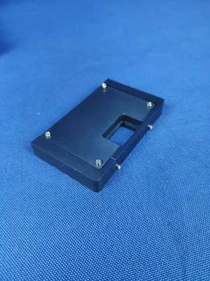
USB Type-C Connectors and Cable Assemblies Compliance - Figure D-1 Example of 4-AxIs Continuity Test Fixture
Table D-1 Force and Moment Requirements
| Receptacle configuration with respect to mounting surface | Force at 15 mm from receptacle shell mating edge (N) | Moment with respect to receptacle shell mating edge (Nm) |
| Right angle | 20 | 0.30 |
| Vertical | 8 | 0.12 |
The continuity across each contact shall be measured throughout the application of the tensile force. Each non-ground contact shall also be tested to confirm that it does not short to the shell during the stresses. The PCB shall then be rotated 90 degrees such that the cable is still inserted horizontally and the tensile force in Table D-1 shall be applied again in the downward direction and continuity measured as before. This test is repeated for 180 degree and 270 degree rotations. Passing parts shall not exhibit any discontinuities or shorting to the shell greater than 1 μs duration in any of the four orientations.
One method for measuring the continuity through the contacts is to short all the wires at the end of the cable pigtail and apply a voltage through a pull-up to each of VBUS, USB D+, USB D−, SBU, CC, and USB SuperSpeed pins, with the GND pins connected to ground. Alternate methods are allowed to verify continuity through all pins.

|
|
| MOQ: | 1 |
| Price: | To be quoted |
| Standard Packaging: | safety carton pack or plywood box |
| Delivery Period: | goods in stock |
| Payment Method: | T/T |
| Supply Capacity: | 10 set/ month |
USB Type-C Connectors and Cable Assemblies Compliance - Figure D-1 Example of 4-AxIs Continuity Test Fixture
Table D-1 Force and Moment Requirements
| Receptacle configuration with respect to mounting surface | Force at 15 mm from receptacle shell mating edge (N) | Moment with respect to receptacle shell mating edge (Nm) |
| Right angle | 20 | 0.30 |
| Vertical | 8 | 0.12 |
The continuity across each contact shall be measured throughout the application of the tensile force. Each non-ground contact shall also be tested to confirm that it does not short to the shell during the stresses. The PCB shall then be rotated 90 degrees such that the cable is still inserted horizontally and the tensile force in Table D-1 shall be applied again in the downward direction and continuity measured as before. This test is repeated for 180 degree and 270 degree rotations. Passing parts shall not exhibit any discontinuities or shorting to the shell greater than 1 μs duration in any of the four orientations.
One method for measuring the continuity through the contacts is to short all the wires at the end of the cable pigtail and apply a voltage through a pull-up to each of VBUS, USB D+, USB D−, SBU, CC, and USB SuperSpeed pins, with the GND pins connected to ground. Alternate methods are allowed to verify continuity through all pins.
address
RM C, 13/F, HARVARD COMMERCIAL BUILDING, 105-111 THOMSON ROAD, WAN CHAI, HK
tel
86-769- 81627526